Safety Demonstration with Fault Tree Analyses
How can a Fault Tree Analysis cover a Safety Requirement?
To analyze the compliance of a previously allocated safety requirement, the system must be broken down into components, and their failures are analyzed to deduce how the system is likely to fail and how often.
In the case where a system is not designed with redundancies, opting for FMECA is convenient. It is easy to implement—each component corresponds to one line, and the sum of all components’ failure rates becomes the system’s overall failure rate. It is a simple and conservative approach, as potential redundancies that could improve the failure rate are not considered.
However, for redundant functions, Fault Tree Analyses (FTAs) are crucial to assess the weight of redundancies. Implementing FTAs requires more experience. Firstly, mastery of FTA logic gates and calculation methods is essential. Secondly, a thorough understanding of the analyzed system is necessary. Meetings with designers should be conducted to ensure that no misunderstandings or overlooked subtleties could lead to inaccuracies in the FTA.
In this section, we will discuss the initial steps toward comprehending the FTA method.
What are the basic principles of a FTA?
Many parallels with Functional Block Diagrams can be drawn, as redundancies are also considered similarly. However, some associative specificities of the FBD make it more adapted for reliability analyses (refer to the section related to Functional Block Diagrams).
The FTA can also be utilized for reliability analyses. The initial step in building an FTA is defining the Unwanted Event, directly derived from the addressed requirement:
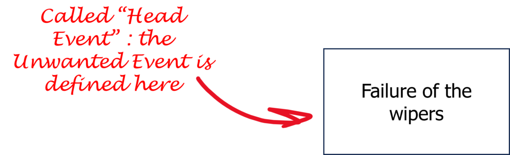
As it implies, a head event sits at the top of the FTA.
Then, a deductive approach is taken to populate the lower blocks. But before delving into that, let’s examine… How?
The logical operators of a Fault Tree Analysis
The most commonly used logical operators are OR, AND, and K out of N also called voting gate These are dysfunctional operators, so they respectively mean:
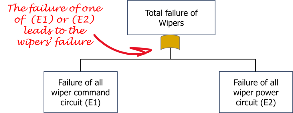
- Under an “Or” gate, “Component 1” or “Component 2” must fail to reach the failed condition. Example: The failure of the engine or an empty gas tank bring the car in a failed state.
- Under an “And” gate, “Component 1” and “Component 2” must fail to reach the failed condition. Example: The failure of the left engine and the failure of the right engine bring the plane in a failed state.
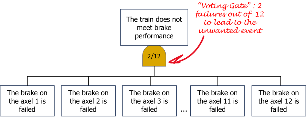
- Under a voting gate, K components out of N are failed, the failed condition is reached. Example: a 12-axel train needs 10 axels with functioning brakes to reach the brake performance target, do is considered failed after the loss of 2 braked axels. This condition corresponds to a “2 out of 12” gate. Indeed, the failed condition is reached only when the number of failed components surpasses the specified threshold K in a “K out of N” system.
Many other gates exist in FTAs, but they are rarely used and won’t be discussed in this section.
The Types of Events in the Fault Tree Analysis
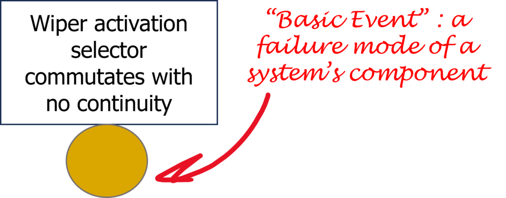
- The basic Event, represented with a circle, corresponds to a failure mode of a component. This failure mode is formally defined and quantified in either a datasheet, a FMECA, or a database.
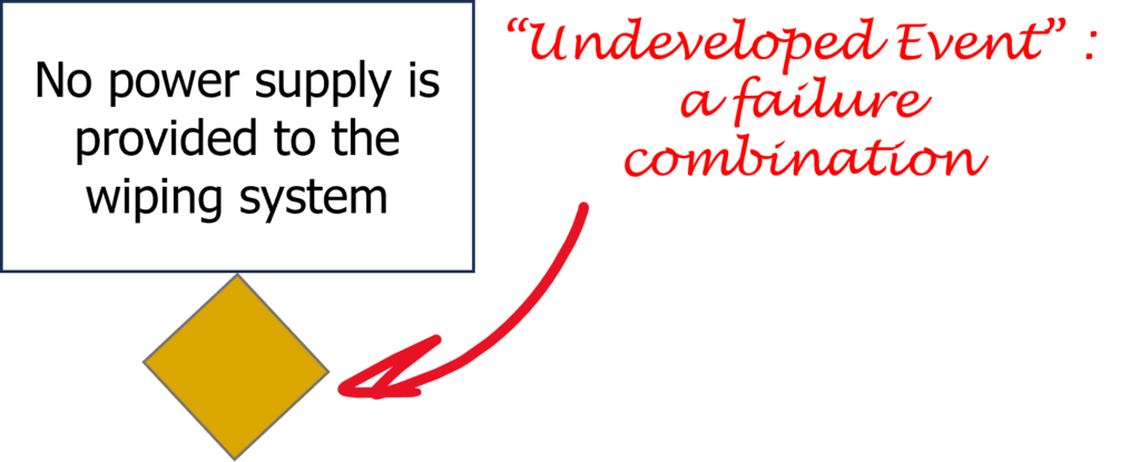
- The undeveloped event, represented with a diamond, corresponds to an event which is estimated in another study. It can be also referring to a part of another FTA, but be careful, no failure mode shall be in common with any other event of the FTA. Each event shall be statistically independent, otherwise the redundances would not be verified. The use of an undeveloped event can be temporary before having further information. No difference with the basic event is implied regarding the calculation formulas.
Many other events exist in FTAs, but they are rarely used and won’t be discussed in this section.
The Structuration of a Fault Tree Analysis
The structuring of the FTA is typically flexible. For the same system, numerous structuring possibilities exist, ultimately conveying the same meaning.
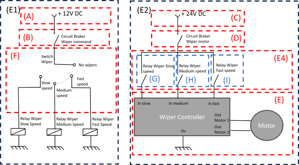
Let’s consider the following architecture:
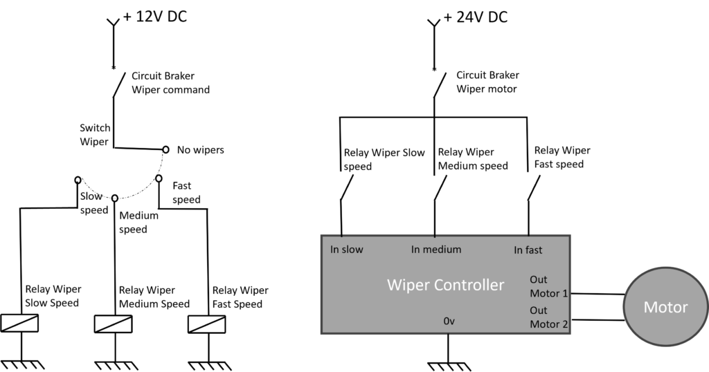
Recall the requirement mentioned in the allocation section: “The function to wipe the windscreen shall be SIL4 and have a failure rate under 1E-9/h.” Now, let’s proceed to prove it!
First, let’s make an initial division of the system. Consider two sub-events: E1, related to the command circuit, and E2, related to the power circuit.
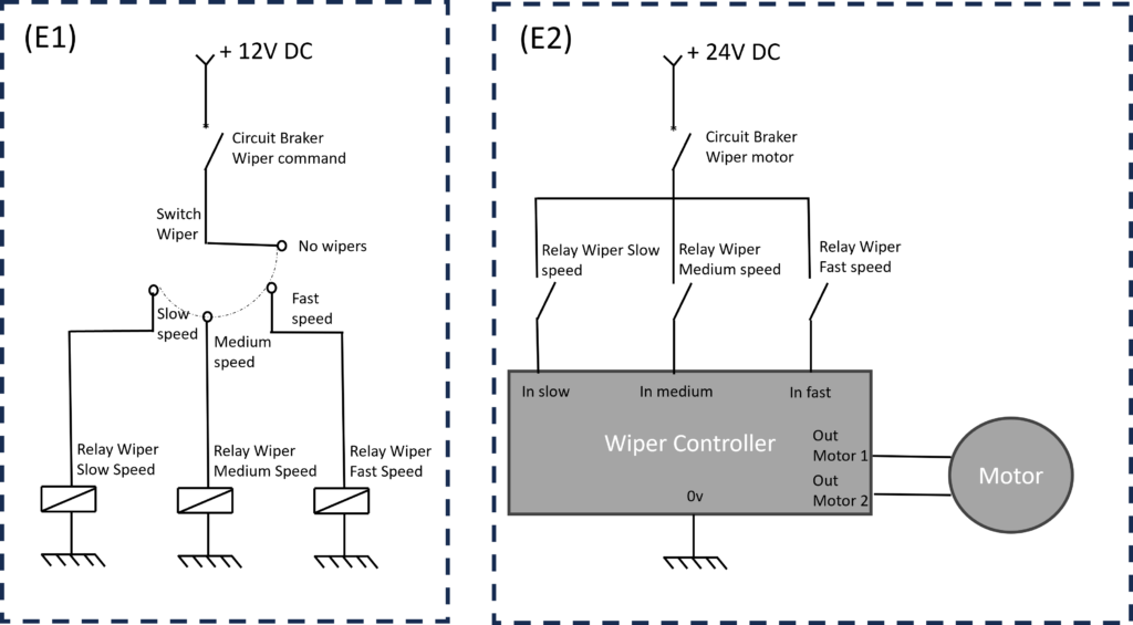
This division is somewhat arbitrary and relies on common sense, but it appears to be the most comprehensive in this case.
- E1 represents the failure of the wiper command circuit.
- E2 represents the failure of the wiper power circuit.
Now, let’s illustrate both events on an FTA:
Now, we need to segment the system into different sections until we reach undeveloped or elementary sections:
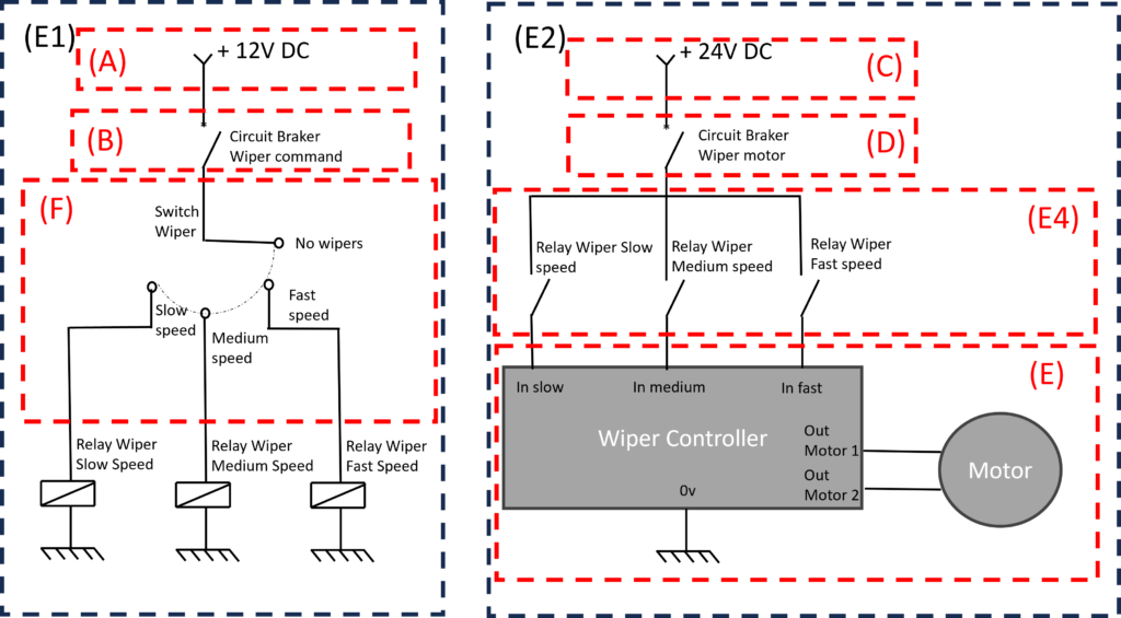
In this step, A, B, C, D, E, and F cannot be further sliced. E4 is the last event to be developed. Note that the relays are depicted in two parts of the schematic, but they are considered only once. Each component is always considered once in the FTA; otherwise, it could lead to inaccuracies.
Here is the FTA for this slicing:
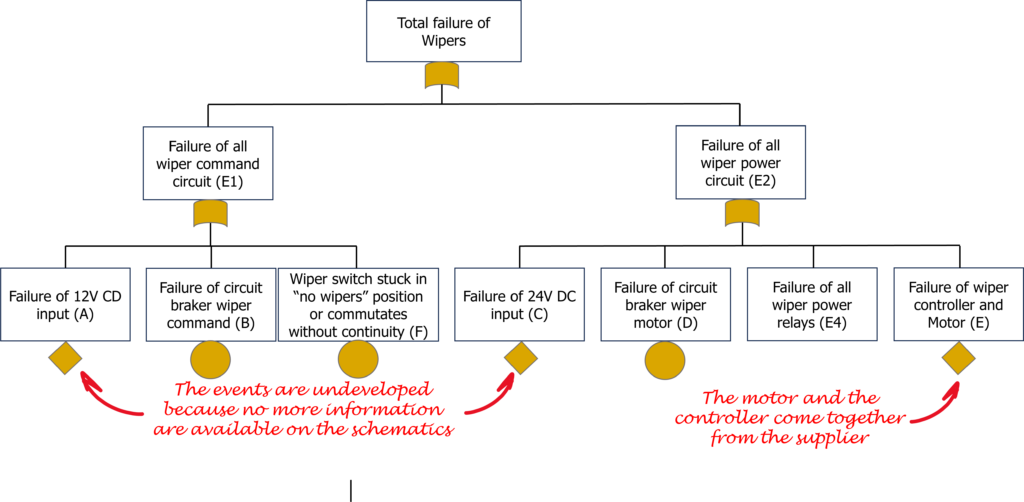
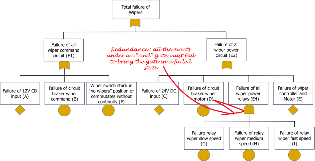
And to conclude, let’s break down the remaining E4:
Here is the final FTA:

This FTA lacks any quantitative values. While this might be suitable for qualitative analysis, such as demonstrating the absence of common modes of failure or compliance with a specific code of practice in terms of system architecture and redundancies, quantitative FTAs are often required, especially when addressing quantitative requirements, as we are currently doing.
How is a failure rate calculated on a Fault Tree Analysis?
For a quick answer, use your favorite FTA software modeler and let it perform the calculations for you. However, keep in mind that certain parameterizations are required beforehand, and delving into these details can be intricate. Refer to the advanced FTA techniques section of the advanced module. Make sure you are comfortable with all the basic notions before diving in.
For a more detailed (yet not too lengthy) answer, let’s explore this in several steps:
How to calculate the cut sets?
Cut sets, as mentioned earlier, are combinations of basic events that, if they occur together, will lead to the top event or system failure. You’ll better understand after a few lines.
But before we proceed, let’s have a quick reminder. Those already familiar with Boolean algebra can skip this part:
Boolean Properties Reminder
As a reminder, in a FTA, “true” represents the failed state.
As seen in the example above in our first FTA, an AND gate produces a true (1) output only when all of its inputs are true (1).
Let’s define E0 as the event at the top of the AND gate, and A and B as basic events.
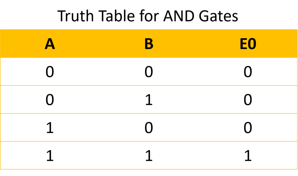
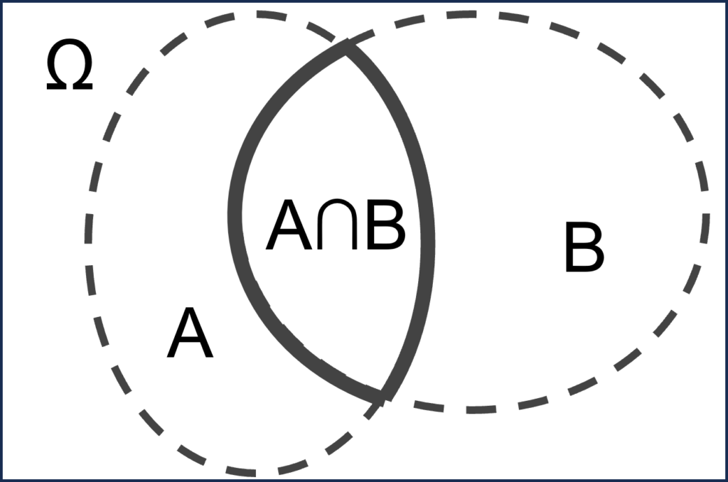
We can note that E0=A⋅B, where “⋅” represents the AND operation, its corresponding mathematical set is “∩” (intersection of two sets).
Indeed, let’s reproduce the above truth table with the “.” Operator, which is a Boolean analogy of the multiplication:
- = 0 : in redounded system (AND Gate), if A has not failed and B has not failed, then the system E0 has not failed.
0.1 = 0 : in redounded system (AND Gate), if A has not failed and B has failed, then the system E0 has not failed.
1.0 = 0 : in redounded system (AND Gate), if A has failed and B has not failed, then the system E0 has not failed.
1.1 = 1 : in redounded system (AND Gate), if A has failed and B has failed, then the system E0 has failed.
Makes sense right?
Likewise, an OR gate produces a true (1) output as soon as one of its inputs is true (1).
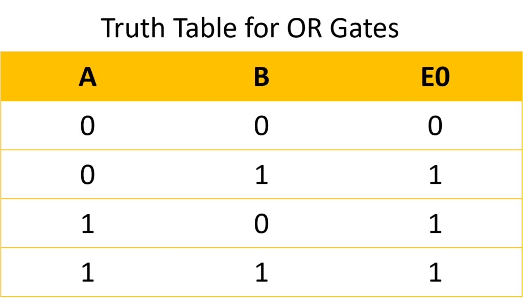
We can note that E0 = A + B, where “+” represents the OR operation, and its corresponding mathematical set is “∪” (union of two sets).
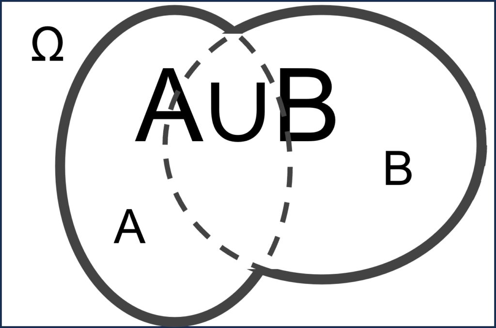
Let’s reproduce the above truth table with the “+” Operator, but the analogy may have already jumped to your eyes:
0 + 0 = 0 : in simplex system (OR Gate), if A has not failed and B has not failed, then the system E0 has not failed.
0 + 1 = 0 : in simplex system (OR Gate), if A has not failed and B has failed, then the system E0 has failed.
1 + 0 = 0 : in simplex system (OR Gate), if A has failed and B has not failed, then the system E0 has failed.
1 + 1 = 1 : in simplex system (OR Gate), if A has failed and B has failed, then the system E0 has failed.
So, finally... How to calculate the cut sets?
As reminded above, let’s write the Boolean formula of our FTA step by step:
The head event is Total Failure of Wipers (E0).
Step 1:
E0 = E1 + E2
Step 2:
E1 = A +B + F
E2 = C+ D + E4 + E
So: E0 = A +B + F + C + D + E4 + E
Then:
E4 = G.H.I
So: E0 = A + B + F + C + D + G.H.I + E
Now, how are we supposed to calculate a global failure rate?
Once again, there is a short and a long answer. The long one is discussed in the advanced chapter for FTA techniques.
The short one is: replace each basic event with its failure rate in the formula. It is an approximation and considers several hypotheses such as:
- The failure of each component shall be detected and replaced within one hour.
- The head event shall be under 10E-3/h; otherwise, it would be too overestimated.
But this is a good start to understand the process!
Let’s remind the context once again. The goal of this FTA is to address the requirement from the Preliminary Risk Analysis: “The function to wipe the windscreen shall be SIL4 and have a failure rate under 1E-9/h.”
To fulfill this, the condition λ_E0 < 10^(-9) must be verified. If it’s not, changes in design need to be considered. Propositions can include adding redundancies or an additional safety system (sometimes requiring changes in allocation), and the design will determine feasibility. Sometimes it is not feasible, and then other criteria such as periodic maintenance or changing the demonstration method need to be considered. All of this is detailed in the advanced section.
The Cut Sets List of a Fault Tree Analysis
The cut sets list is crucial for determining the contribution of a basic event to the global failure. The smaller the cut set order, the more critical it is. This list is determined by separating terms linked with the “+” operator and gathering terms with the “.” operator in the global logical equation of the FTA: A + B + F + C + D + G.H.I + E becomes A, B, F, C, D, GHI, E.
A, B, F, C, D, E are single; each represents a cut set of order one, meaning if they fail, the whole system fails. A cut set of order one is called “a single failure” and requires special attention. They are even listed in a dedicated document called the “Safety Critical Item List,” discussed in the advanced section. They should be avoided if possible.
In our example, there is no cut set of order two, also known as “Fail Safe,” because if one component fails, the other can still support the function. For example, a plane has a fail-safe propeller system: if one motor fails, the second is sufficient to bring the plane to its destination.
GHI is the only cut set of order three, also called “Fail Safe-Fail Safe.” Even after two failures, the system can rely on the third remaining redundant component to operate. In our example, even if the medium and fast-speed relays fail, the slow-speed relay can still perform the function. Although having only the slow-speed relay degrades the function and will require a significant reduction in speed. A “Fail Safe-Fail Safe” system is the minimum required cut set for nuclear catastrophe risk assessment.
There is no cut set above the third order. In any case, mentioning them is often not mandatory due to the low risk they represent.
Refactoring of Fault Tree Analysis logical function
In our example, the cut sets list is easy to deduce and did not require refactoring. Each event appears only once in the FTA. But in cases where some events happen several times, refactoring becomes necessary.
When a basic event appears multiple times in all “AND gates” of a system intentionally designed to be redundant or appears under the top event, it is called a Common Mode of Failure. It can be accepted if its failure rate is negligible in regard to the global objective. Common Mode of Failures has wider implications, as discussed in the advanced dedicated part, but this term is commonly used for this purpose. Here is an example:
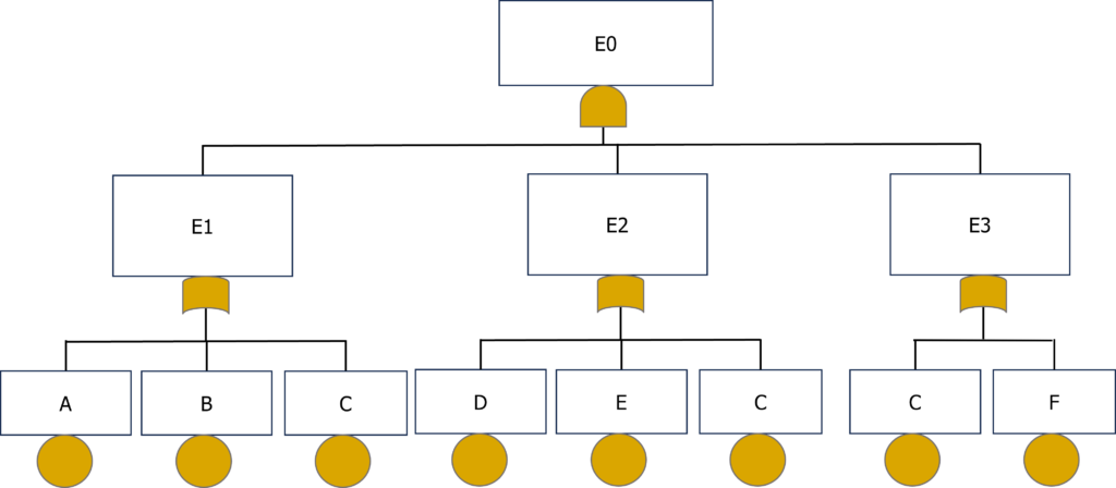
It is noteworthy that C appears several times in the FTA, and especially under all redundances: it is a common failure mode. The FTA and it could be refactored into this:
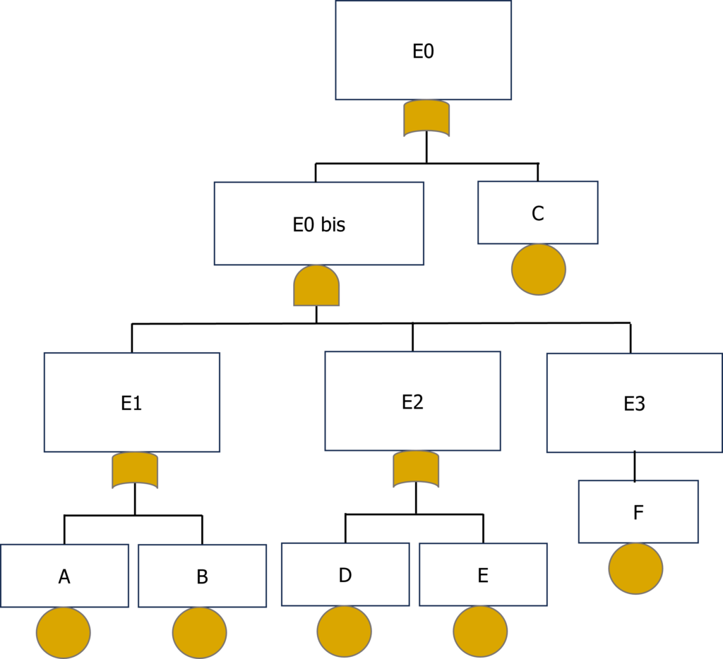
Here is the logical formula of the first FTA:
E0 = E1.E2.E3 = (A + B + C) . (D + E + C ) . (C + F) = C + ((A + B) . (D + E) . F) here is the formula of the second FTA found again. But to have the list of cut sets, new developments and factorizations are necessary to isolate all the cut sets:
C + ((A + B) . (D + E) . F) = C + ((A.F + B.F) . (D.F + E.F))= C + A.F.D.F + A.F.E.F + B.F.D.F + B.F.E.F
In set-theoretic operations, the absorption characteristic is applicable: A ∪ A = A, so the redundant F are reduced:
C + A.F.D + A.F.E + B.F.D + B.F.E
That’s it, the formula is completely developed, the cut sets can be isolated:
C is the only cut set of order 1
There is no cut set of order 2
AFD, AFE, BFD, BFE are the cut sets of order 3
As we did for the wipers example FTA, here is the (oversimplified) failure rate calculation formula of this FTA:
Further mathematical explanations are available in the advanced section, particularly to understand how preventive maintenance can influence the failure rate of a system.
Do you want to be an expert in Fault Tree Analysis calculation?
I can advise you to visit the documentation of Arbre Analyste FTA where further passionate details about how statistical, probabilistic, and combinatory calculations are computed.